7/18/18: Exterior Woodwork II
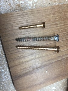
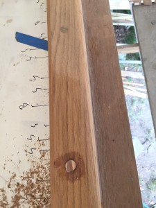
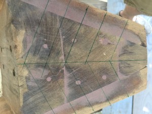
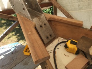
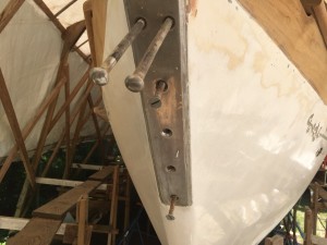
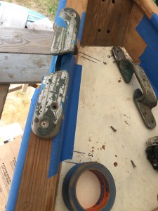
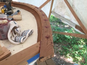
The small screw in the photo below is one of the #12, 1 3/4″ bronze wood screws used to fasten the cap rails. The larger screws are old and new screws used to fasten the genoa track to the rails. The larger screws are #16, 3″.
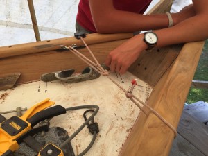
As discussed previously, the rails are bent from the ends until the next screw location (possibly far from an end) is in position.
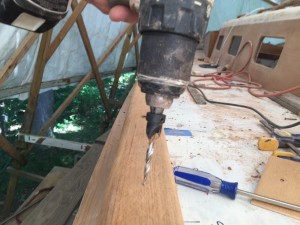
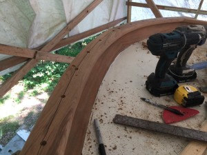
Once a particular screw location is in place, I drilled the pilot hole using a tapered bit with a countersink.
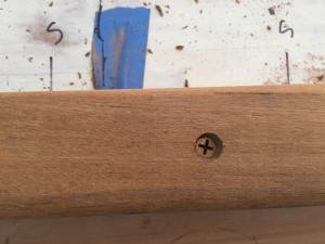
Next, I used another drill with a phillips bit to sink the screw, then a screwdriver for final tightening.
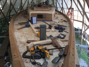
Here the starboard and port rails are fastened. (Incidentally, I used Dolfinite as a bedding compound, but there will be more on that later.)
There were 118 screws, so we cut 118+ bungs and set them in thickened epoxy. The next day, I chiseled off all but about 1/8″ of each bung then sanded off the rest.
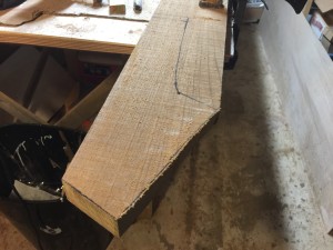
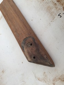
There is a gap in the rails at the bow, where chocks are inset. Forward of the chocks is more teak cap. I began these pieces by roughly tracing the old and cutting out of rough stock.
Next, on the boat, I made a centerline on the stem.
After plenty of planing, sanding, and routing, I was able to temporarily screw the pieces to the stem, as show below.
Final fastening involved thickened epoxy and bungs, and masking tape. (In case you missed it, there was more routing between the above and blow pictures.)
The next challenge was to shape the wood to accept the stem fitting and chocks.
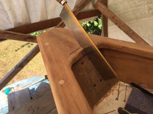
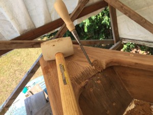
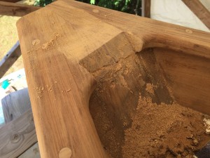
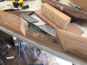
Little by little, I chiseled out material, as shown in the following three photos.
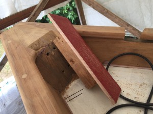
After rough shaping, I made a sanding block out of wood, screws, hot glue, and a used sanding belt.
Eventually I was able to get the stem fitting in place…
…and confirm that the fasteners would find their holes.
The recesses for the chocks presented a different challenge.
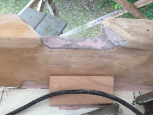
In the photo below you can see that the rail has a slight recess to accept the “wings” (for lack of a better term).
The challenge is that (1) my rails are 1/8 inch thicker and (2) I really don’t feel like cutting recesses. Thus, the bottom of the chocks will sit above the cutouts in the toe rail.
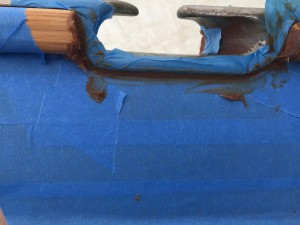
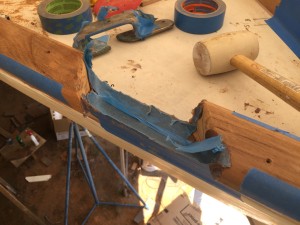
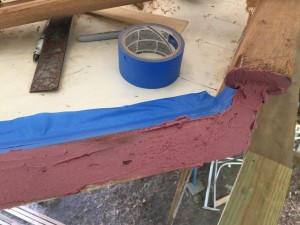
I solved this problem by injecting thickened epoxy into the gap, creating a surface on which the bottom of the chocks will sit.
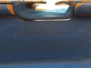
I taped off the bottom of the chocks and some of the surrounding wood before injecting the epoxy.
After the epoxy dried, I was able to remove the chocks by banging on them with a rubber mallet.
After some gap-filling, the job was done.
Here the chocks are in place only temporarily.
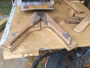
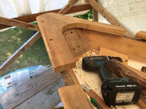
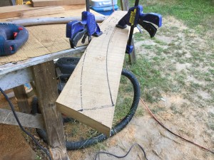
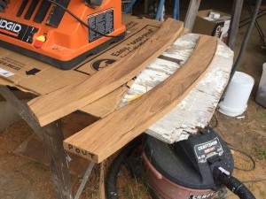
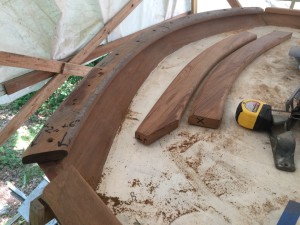
Meanwhile, at the aft end of boat, work began on the wider, curved rail. This rail cannot be made by bending a straight piece, as the curve is too severe, and the rail too wide. I used the old rail as a template and cut the new rail as two pieces out of rough stock,
I cut the shape roughly with the jig saw, then used the table sander to fine-tune the curves. Here are the two pieces planed to thickness.
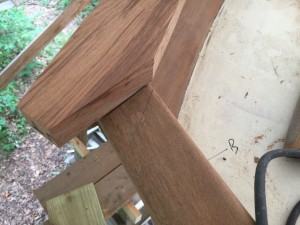
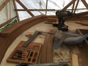
I had to match up these pieces with the starboard and port rails.
Here is the original rail sitting in its original location.
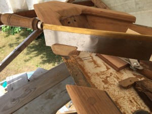
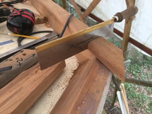
After quite a bit of careful cutting with the dovetail saw, I was able to make a dry fit.
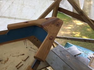
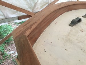
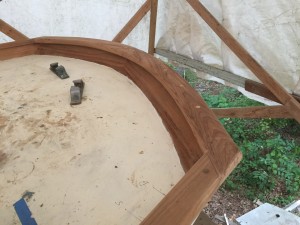
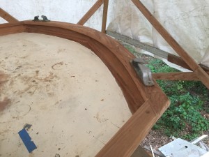
Final installation involved thickened epoxy.
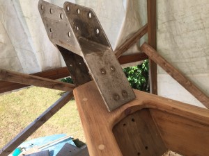
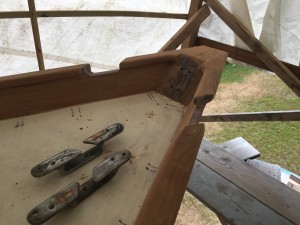
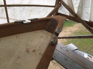
The following photos should, by now, be self explanatory.
Eventually I will reinstall the stern chocks.
