7/28/19: Rudder
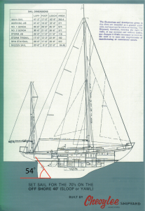
The Offshore 40 rudder is triangular in shape and the bottom is horizontal and even with, and parallel to, the bottom of the keel. You can see this in the profile drawing below (where I’ve indicated the angle the bottom of the rudder makes with the rudder post).
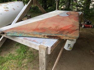
Thalassa’s rudder has been in the basement since 2014, but the time is right to consider its condition and the necessary steps to correct any problems.
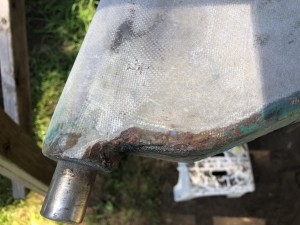
The rudder is a stainless steel post and skeleton and a fiberglass shell filled with foam. I noticed right away that the fiberglass covering the bottom had worn through on the aft end.
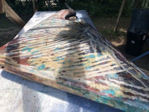
I used chemical stripper, scrapers, and sanding to remove the majority of the bottom paint.
There is some indication of rust on the bottom end.
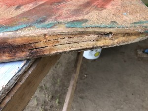
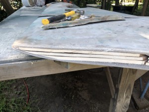
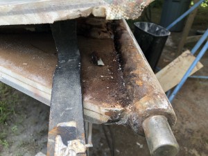
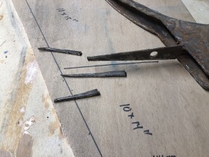
I began exploring by cutting about an inch off the bottom. which exposed three stacked layers of foam. The foam layers were not adhered to each other, but they were dry.
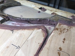
Taking the rudder apart completely is the only way to conduct a proper inspection. Besides, the fiberglass skin was wavy and thin away from the edges, suggesting that a repair had been done at one point.
The foam core further up the rudder was the pour-in/expanding variety, and that there were two distinct foam core systems was strong evidence that the rudder was repaired at one time. It was easy to see that the foam panels near the bottom were part of the repair, while the pour in foam was part of the original build.
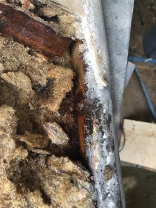
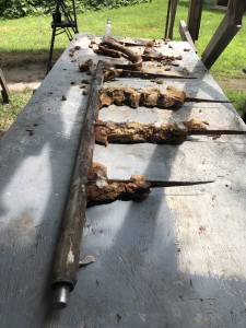
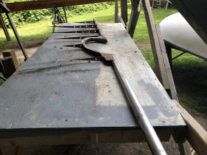
Here is the post/skeleton where you can see the pour-in foam is stuck to the ribs. The ribs are welded to the post and help transfer the torque generated by the steering mechanism to the rudder panel.
There was plenty rust, but it was all surface rust and I cleaned off as much as I could with scraping, sanding, and grinding.
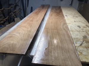
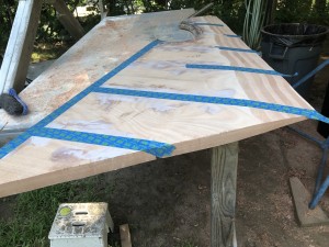
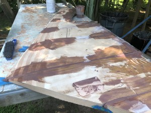
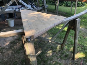
Since I had no intention of reusing the original fiberglass shell, and no access to the original molds (which likely no longer exist, and if they did they might be in Hong Kong), I needed to build the rudder core-first. I started by laminating up (with epoxy) some marine plywood to the desired thickness. Below the two panels have epoxy applied and my next step was to flip the panel on the right over to the left, to make a stack of three, and eventually line up and clamp with many clamps.
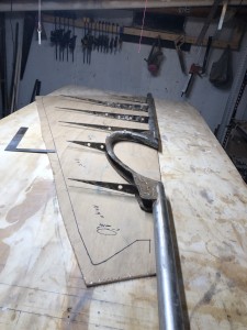
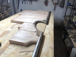
Obviously I traced the shape of the rudder before dismantling it. Here I’ve laid the post/skeleton onto the trace.
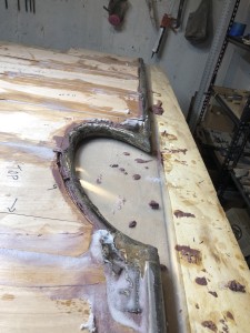
The panels will be installed between the ribs. You can see in the photo above that in some places the panels meet the round post, and that two panels will meet the curved open post in which the propellor sits.
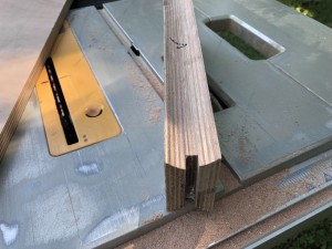
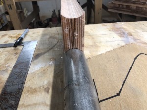
I started by cutting the panels to rough dimensions. I ran the edges that will be against the post over the table saw, at an angle, gradually raising the blade until a suitable hollowed-out profile was formed. Of course there was plenty of trial and error necessary to find the correct position and orientation of the fence.
Eventually, though, I got a good fit. (Note that a perfect fit is not possible. The reason the same as why the rim of a drinking glass only appears as a circle if you’re looking straight down on it.)
I made patterns for the panels that fit into the curved sections. These panels “slot into” the metal part, so I had to rout out the male part of the slot in the wood.
Here is a dry fit of the seven panels.
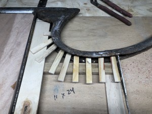
The ribs are triangular in shape and the very ends of some of them were a bit bent, and I decided to cut a few inches from all of them.
Next, I filled the hollow of the curved section with thickened epoxy, and applied it elsewhere as necessary.
Next, I assembled the panels the and filled some of the gaps as a means to secure them to the ribs.
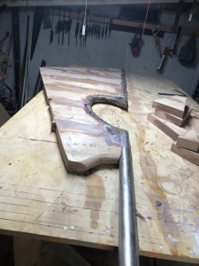
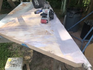
Before finishing the gap-filling, I decided on a profile for the trailing edge, using a section of the original as a guide.
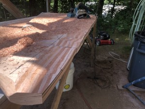
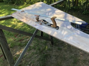
The power planer was indispensable here…
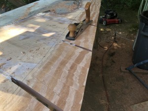
…but hand tools are best for the finer work.
I taped off the gaps on one side…
…before finishing the filling on the other.
Plenty of filling and fairing followed, especially neat the post.
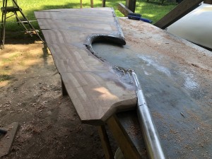
Checking for straight and level revealed that it was almost straight and level.
Checking the shape with the trace revealed that the shape was still good.
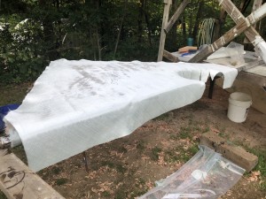
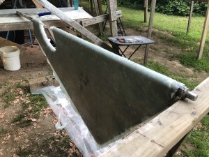
There will be two layers of 17-ox biaxial glass everywhere, but more near the post, which is accomplished by simply letting the layers wrap around the post somewhat.
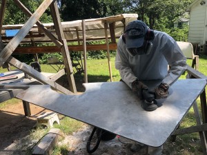
There will be a number of rounds of filling and fairing after the initial sanding.
