6/4/23: Steering
I’m discontinuing the “weeks to go” titles in favor of titles more descriptive of the content of the post. The reason is so that I can more easily find website content for reference. This post would have been “4 weeks to go” and the project is on track for that, though a one- or two-week delay is not out of the question.
This post concentrates only on the steering system. Several other projects are underway, but those will wait for next week’s post.
RUDDER AND STEERING
The last time we discussed the rudder was in THIS POST, in which I discussed boring holes for weight reduction and increased flexibility, and sanding the rudder post so that the bronze rudder port (pictured below) would fit.
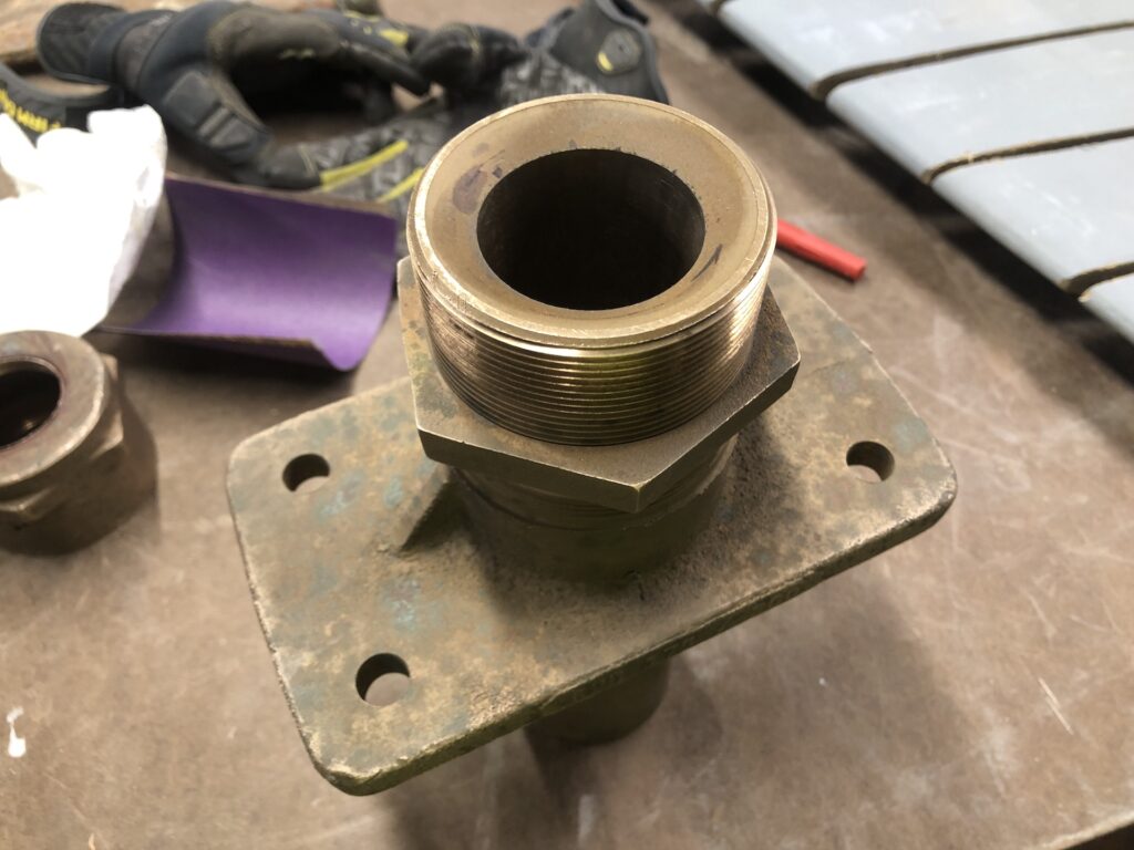
It’s now time to get the rudder installed. I began by dry-installing the rudder port, then digging a hole under the boat to allow the top of the rudder post to slide up into the port:
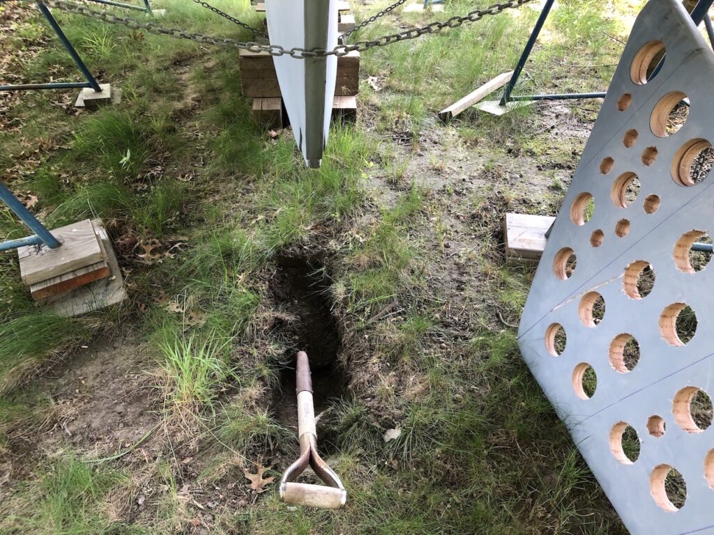
I was concerned about encountering a big rock that would require me to wait until the boat was in a boatyard to complete the installation. In this case, the boat would have needed to be supported high in the slings of a travelift while the work was done. Not ideal. Luckily I encountered only a giant PVC pipe:
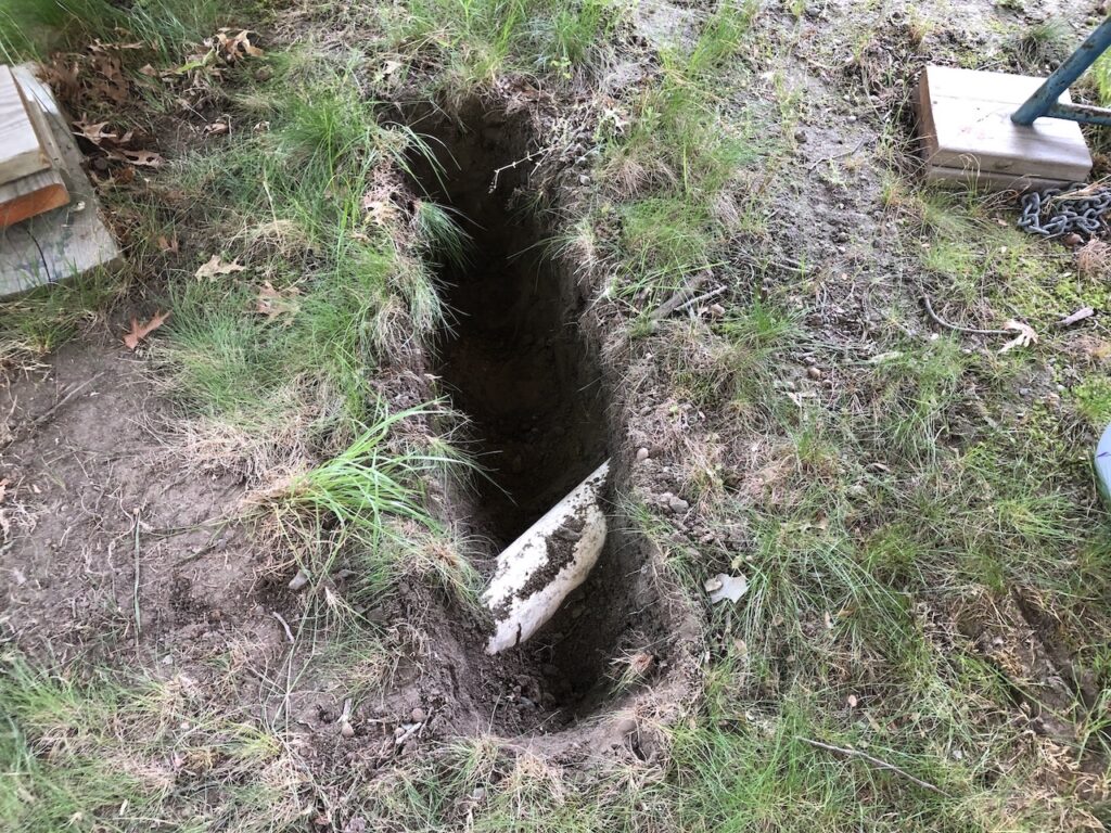
I traced the pipe back to the garage and determined with almost 100% certainty that this is a drain pipe for the garage roof runoff. I estimated this arrangement to be overkill for a roof drain and cut the pipe with no second thoughts:
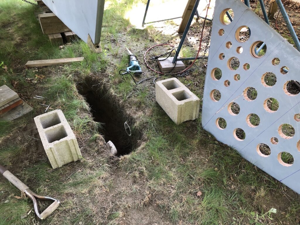
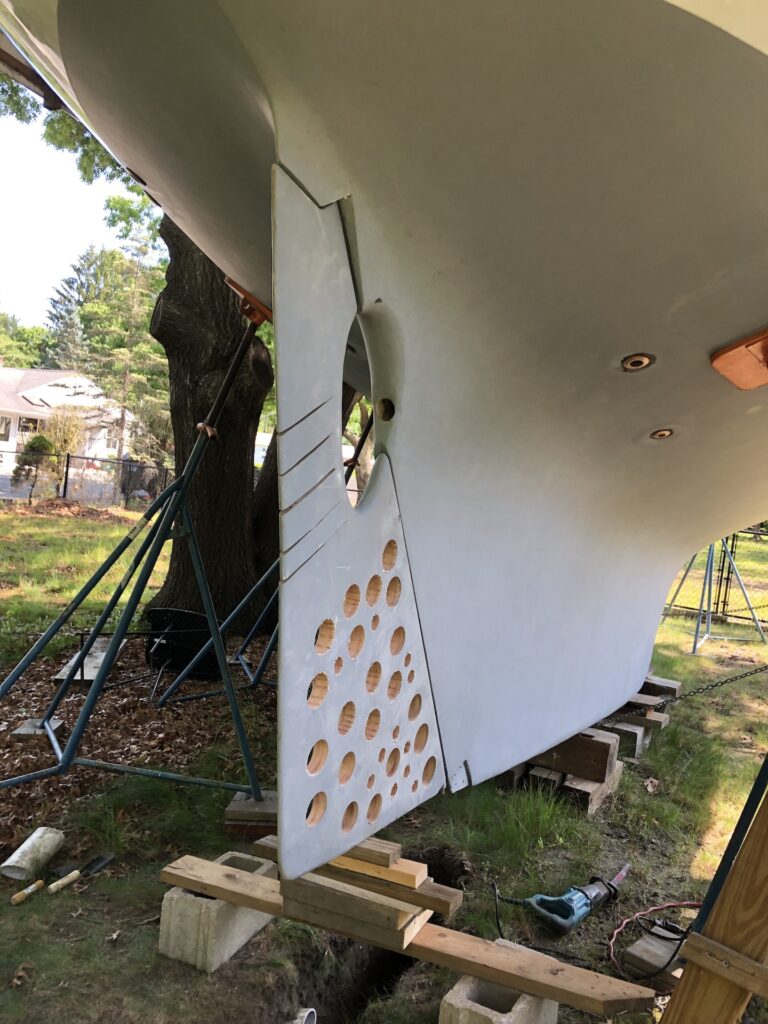
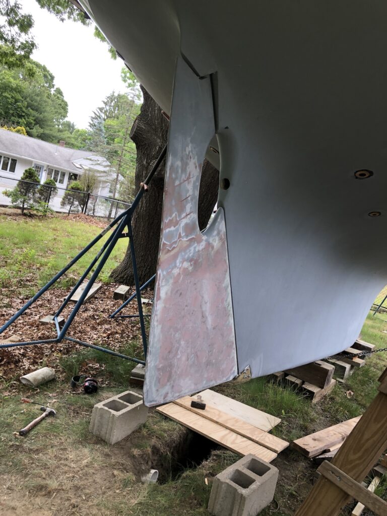
Here the rudder is inserted into the rudder port with its weight supported by cinder blocks and boards:
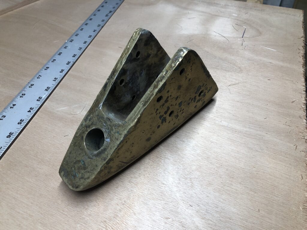
Here is the bronze rudder shoe in which the pin at the bottom of the rudder post turns:
Here the rudder shoe is dry-installed, completing the dry fit of the rudder:
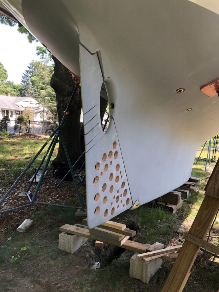
You may recall that one of the issues with the rudder is that the upper and lower posts were not perfectly aligned and there was considerable friction in turning the rudder by hand (the last dry fit of the rudder was in 2019, and you can read about it HERE). One of several corrective measures I took was to cut slits around the propellor “cutout” area to allow some flexibility. I’m happy to report that, for whatever reasons, there was minimal resistance to turning in the above dry fit.
Next, I removed the rudder again in preparation for the next fit, which was not 100% dry. In this case I bedded the port in thickened epoxy:
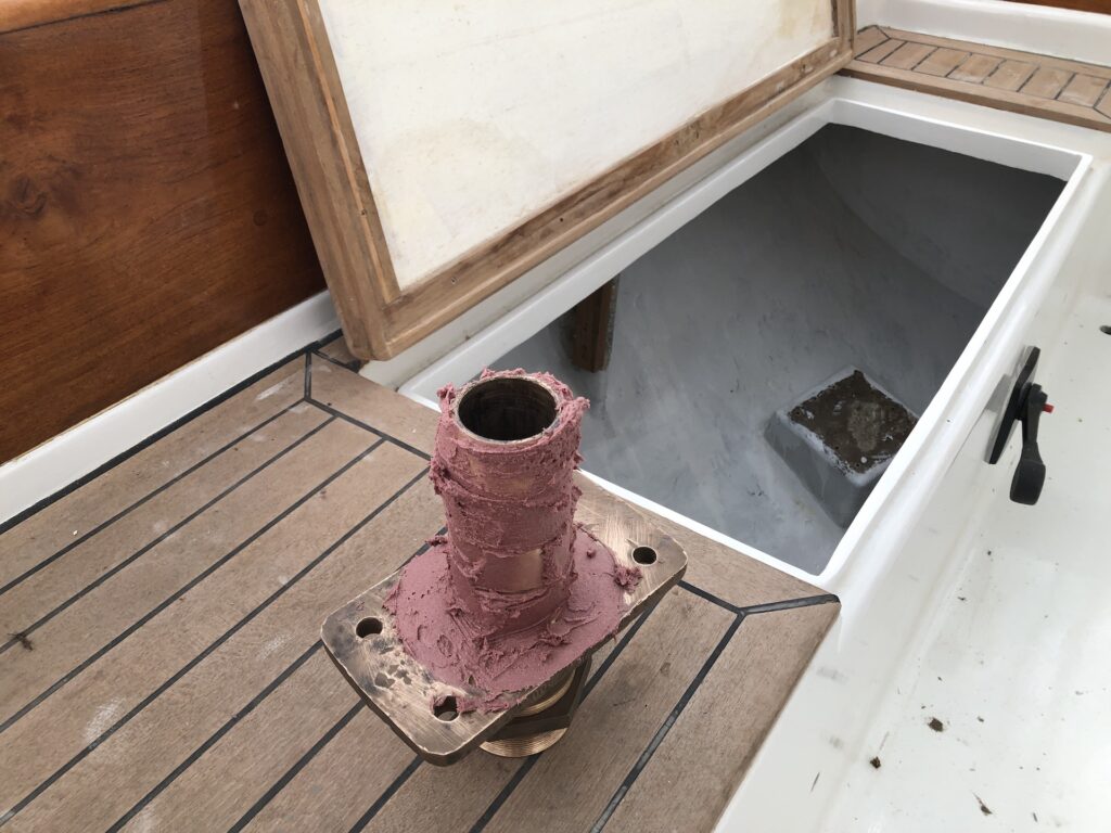
I installed the port and then the rudder. In this way, the epoxy will dry with the port in the correct alignment. A day later, I removed the rudder again and bolted the port to its base. The existing bolt holes were a bit too far out, so I drilled new holes closer to the axis:
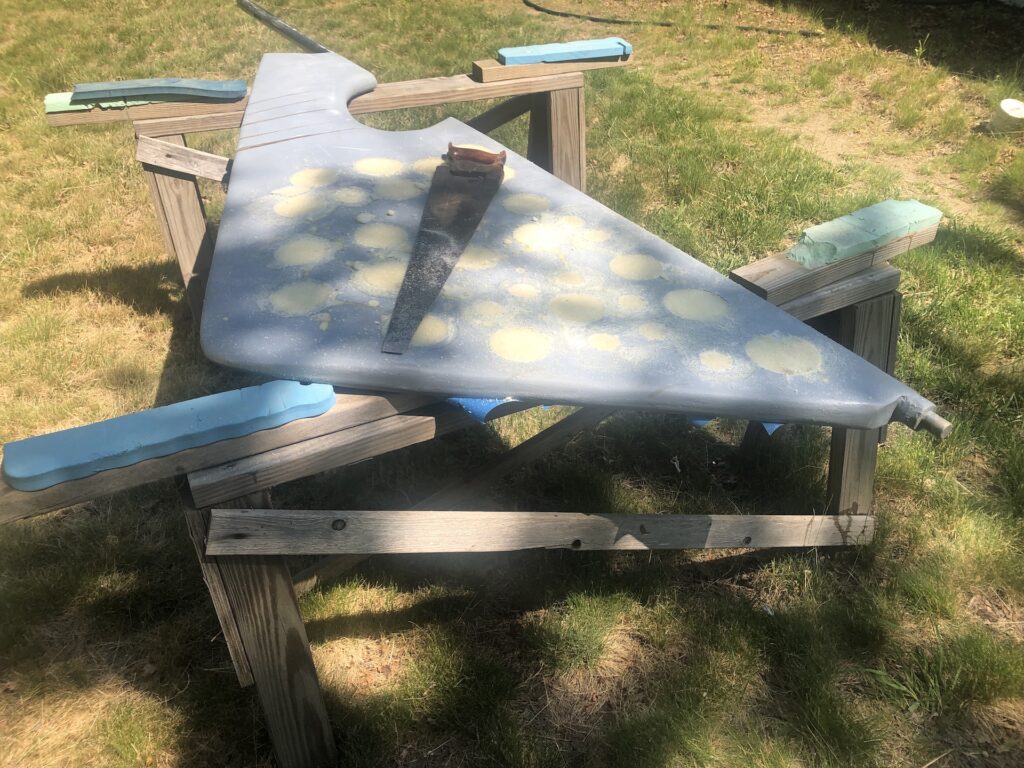
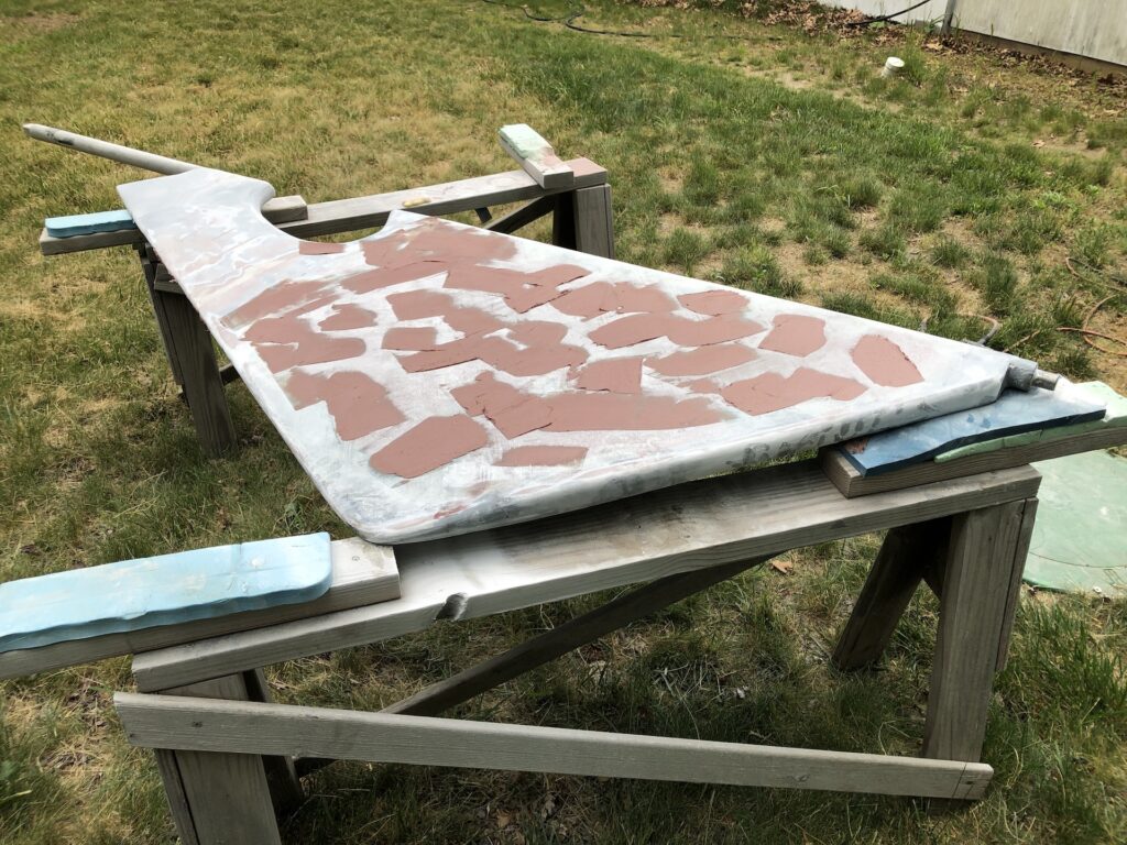
With the rudder on sawhorses, I taped over the holes, flipped the rudder over and used expanding foam to fill the holes. After drying, I cut off the excess with a saw:
Now a layer of glass, and filling the grooves with thickened epoxy:
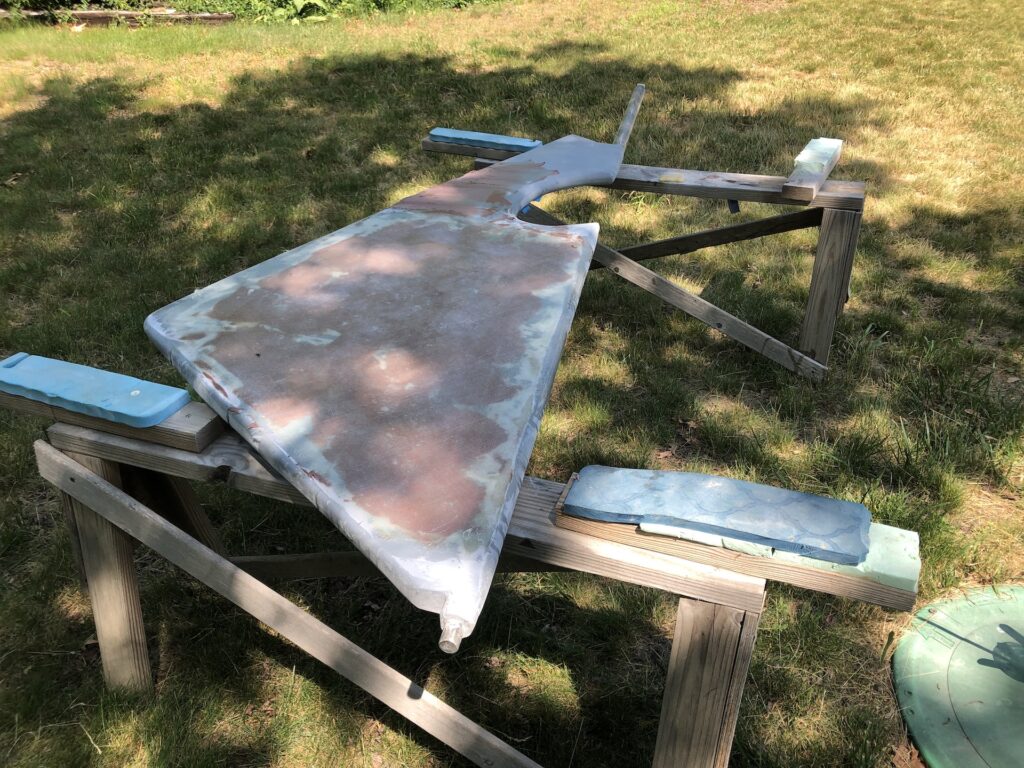
Glass on both sides, of course:
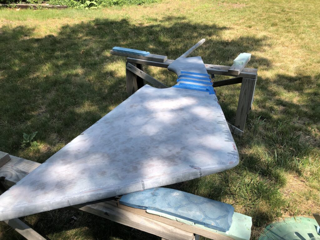
A round of fairing to even out the bumps:
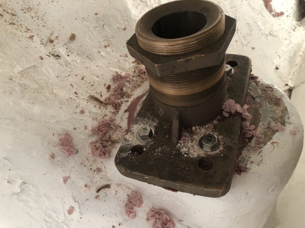
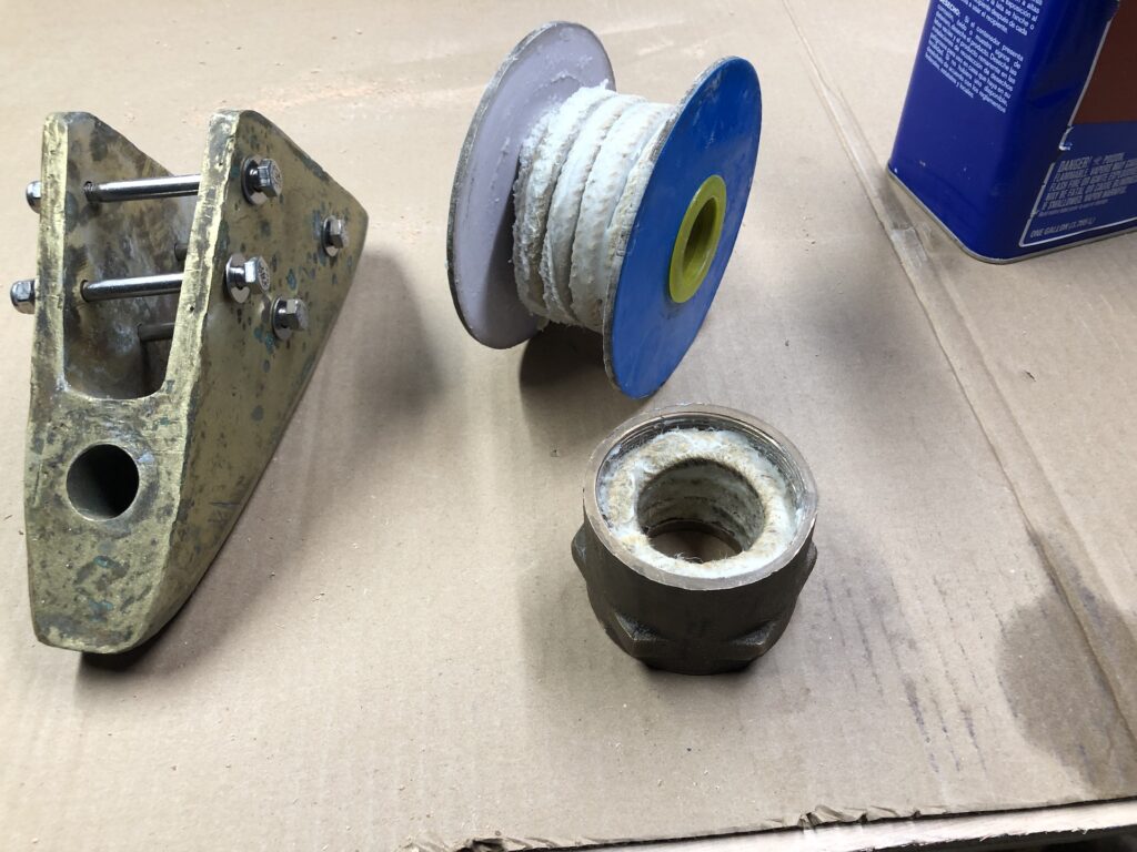
In the final installation, the top nut of the packing gland needs to be slid over the rudder post as it enters the under-cockpit area. I’ve had a roll of the appropriate flax packing, and I packed the gland in advance, which is far easier than wrestling with it later. Here I’ve packed the gland with three loops of packing (lower right in the image below). The cuts are offset from each other so as not to create a channel in which water can flow.
Here the rudder is installed, and the rudder shoe is bolted and bedded in sealant:
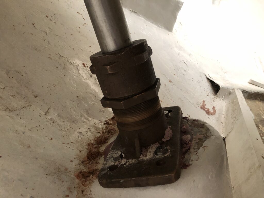
Under the cockpit, the top of the packing gland is threaded down onto the rudder port. When tightened, the packing is compressed and expands to form a seal to keep the ocean out of the boat.
The image below shows the quadrant, sheave housings for the steering cable, and something that stabilizes the bottom of the pedestal post (and also a preview of the hanging-locker doors in the background).
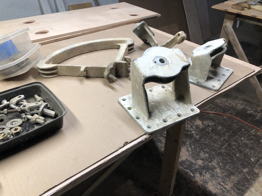
The sheave housings are mounted with screws.
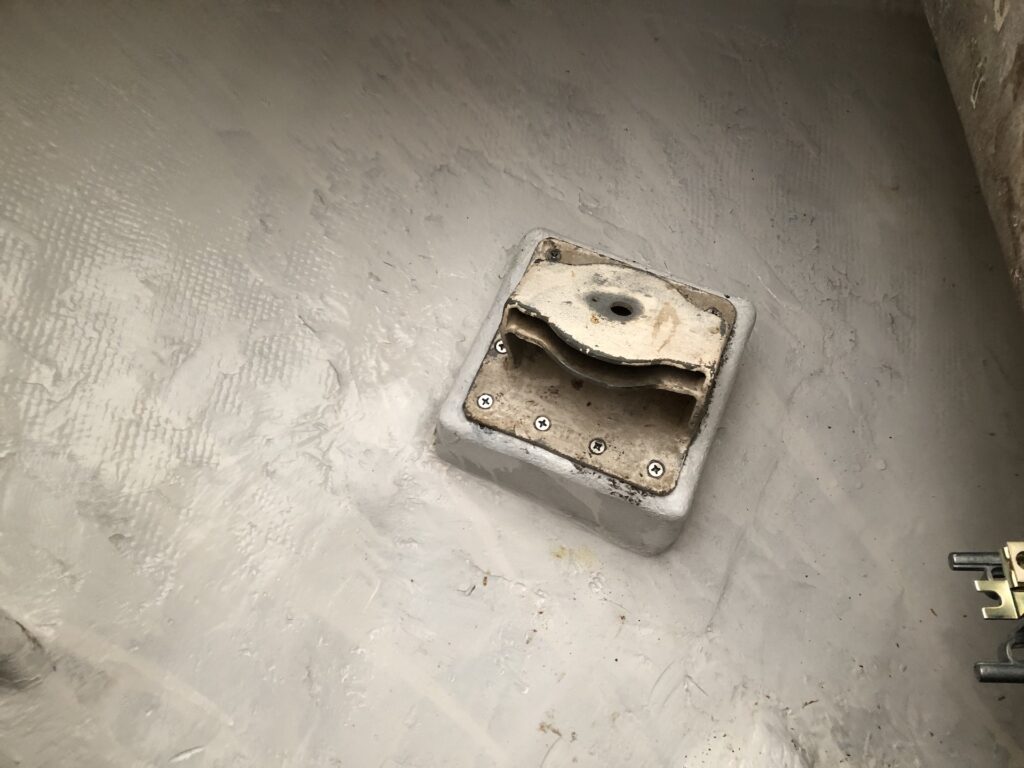
The wires are run through the housings, then the sheaves installed. The quadrant is bolted around the rudder post and “keyed” into it.
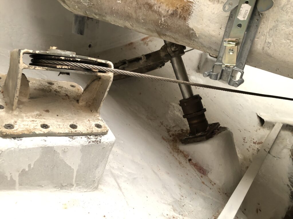
Looking across to the port-side sheave:
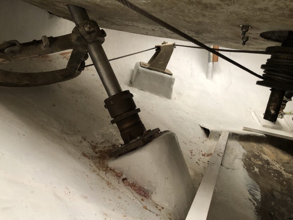
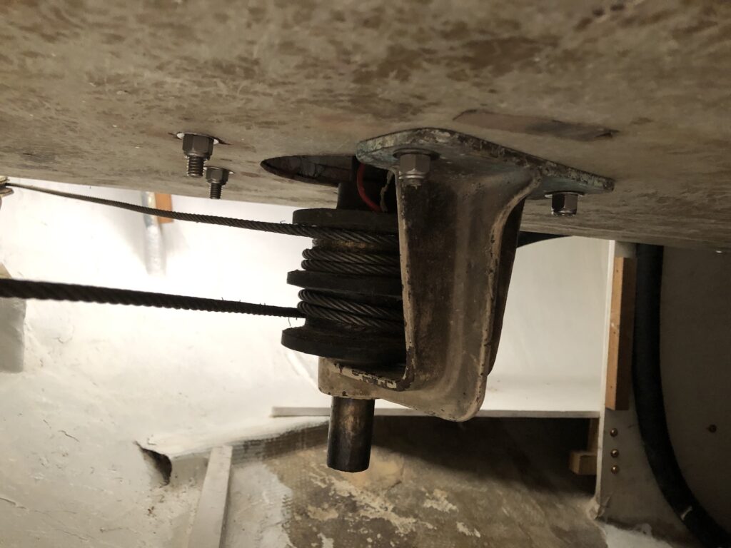
I installed the stabilizing bracket in its original orientation, but found that doing so introduced a lot of steering friction.
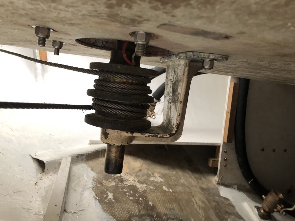
When I installed it in a 30-degrees-rotated orientation there was little to no additional friction:
Meanwhile, outside the boat, I added a layer of glass on each side of the rudder where the “flexibility slits” had been cut. They have been filled with thickened epoxy, but the upper rudder post transfers all of the torque to the bottom of the rudder and a little more strength in this area can’t hurt.
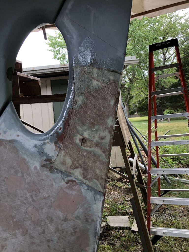
Finally, I sanded it down…
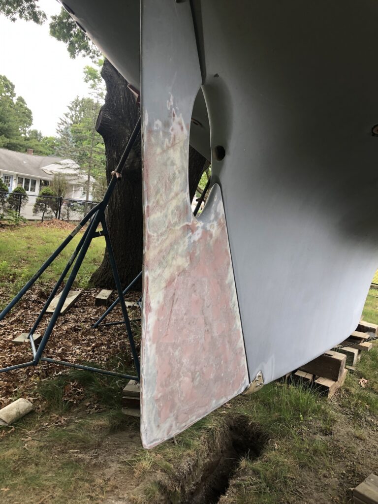
…and painted with the gray barrier-coat primer I used on the rest of the bottom.
