3/18/23: Rudder, Head Plumbing
RUDDER
The rudder was rebuilt in summer 2019 (click HERE and HERE for a review of that work). One of the issues I discovered was that the upper and lower posts of the rudder were not precisely alined. The rudder had suffered some sort of impact at one point in the boat’s previous ownership, which is likely the cause. I did not notice the misalignment until after I rebuilt the rudder (unfortunately). My hopeful solution is to cut some horizontal slices between the posts, install the rudder, and then fill and glass the gaps. The slices, which can be seen in the photo below, should make the rudder more flexible and will hopefully allow the posts to align.
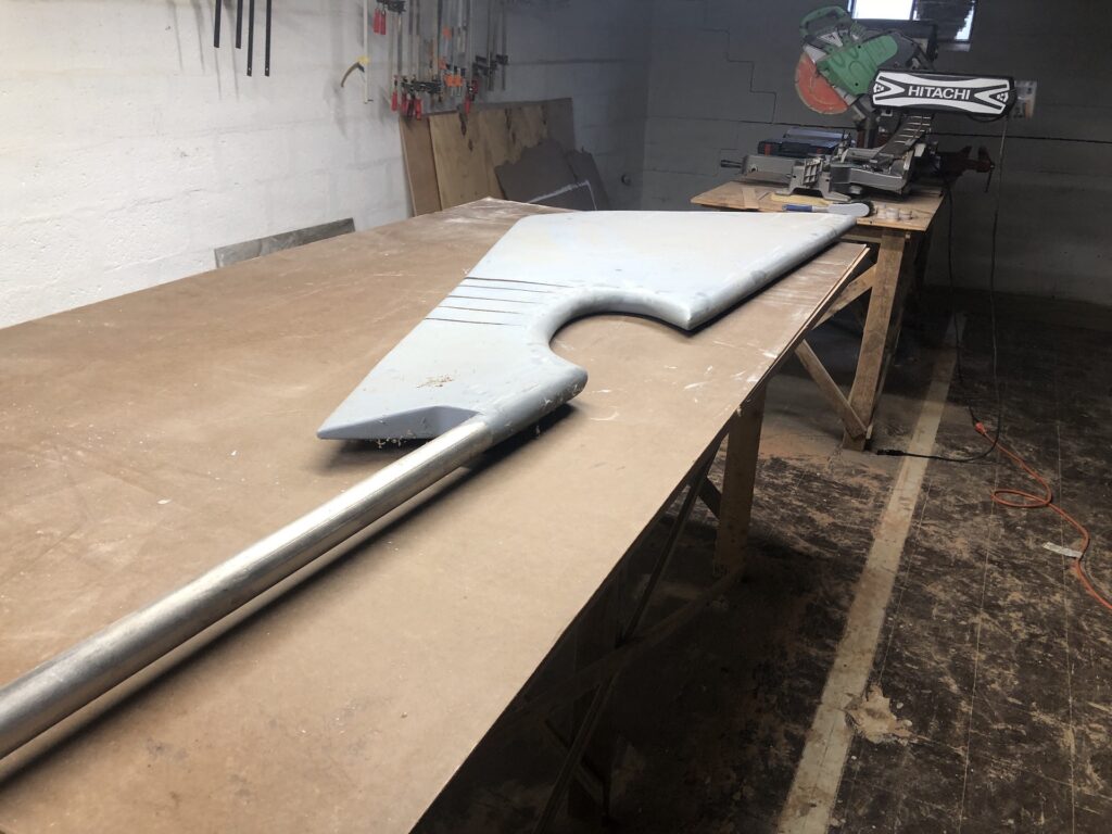
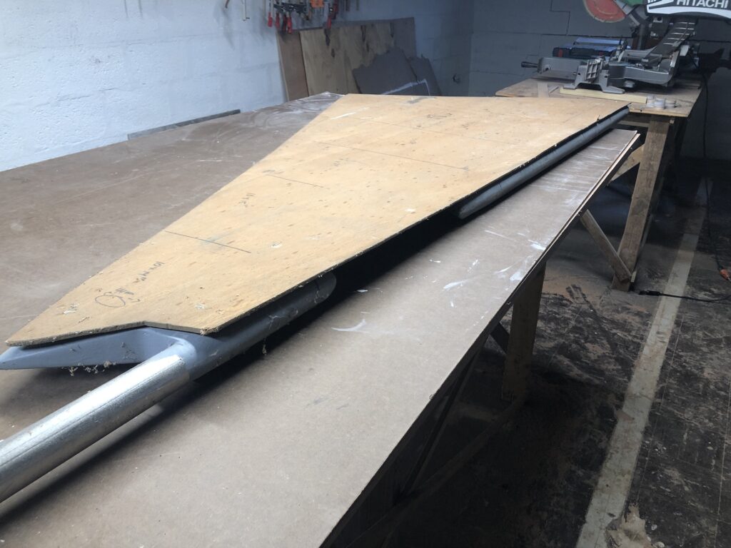
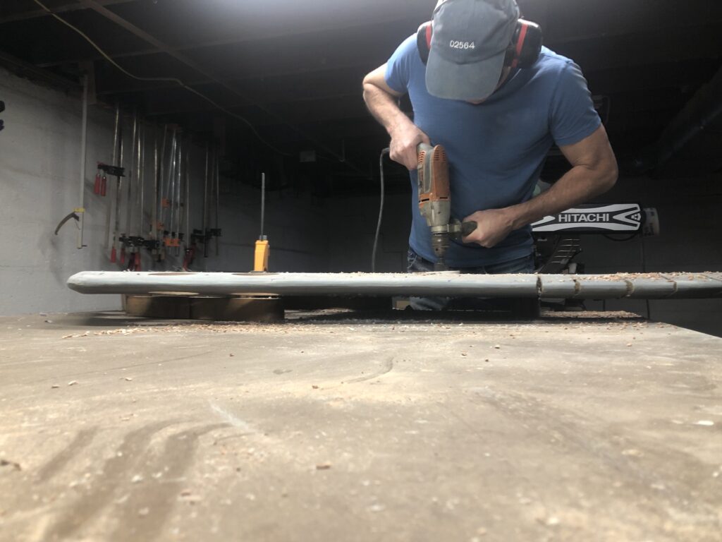
Since I rebuilt the rudder I’ve had second thoughts about the method, in which the core is essentially solid wood. One concern is about the overall weight, but this concern is minor. (I estimate that the rudder will displace about 75-100 pounds of water, resulting in an equal upward buoyant force of 75-100 pounds.) A second concern is the lack of flexibility. In the event of an impact to the rudder, one that is more flexible will transfer less force to its connection points. As a means to make the rudder more flexible, I decided to bore out holes and fill them with expanding foam and glass over. I saved an old patters of the original rudder that includes lines for where the steel “teeth” extend outward from the posts. In this way I was able avoid them while boring.
Hole sawing is not only tedious, but potentially dangerous when using a powerful drill. If all teeth catch at once the drill will attempt a powerful rotation, which can easily break a wrist. My solution, which worked well, was to start lightly, then stop and drill out around the perimeter with a normal bit, then bore out the hole.
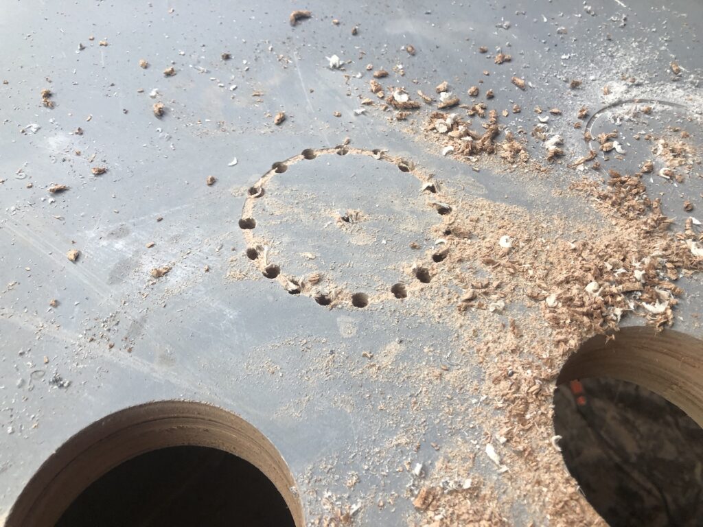
The photo below shows the final pattern.
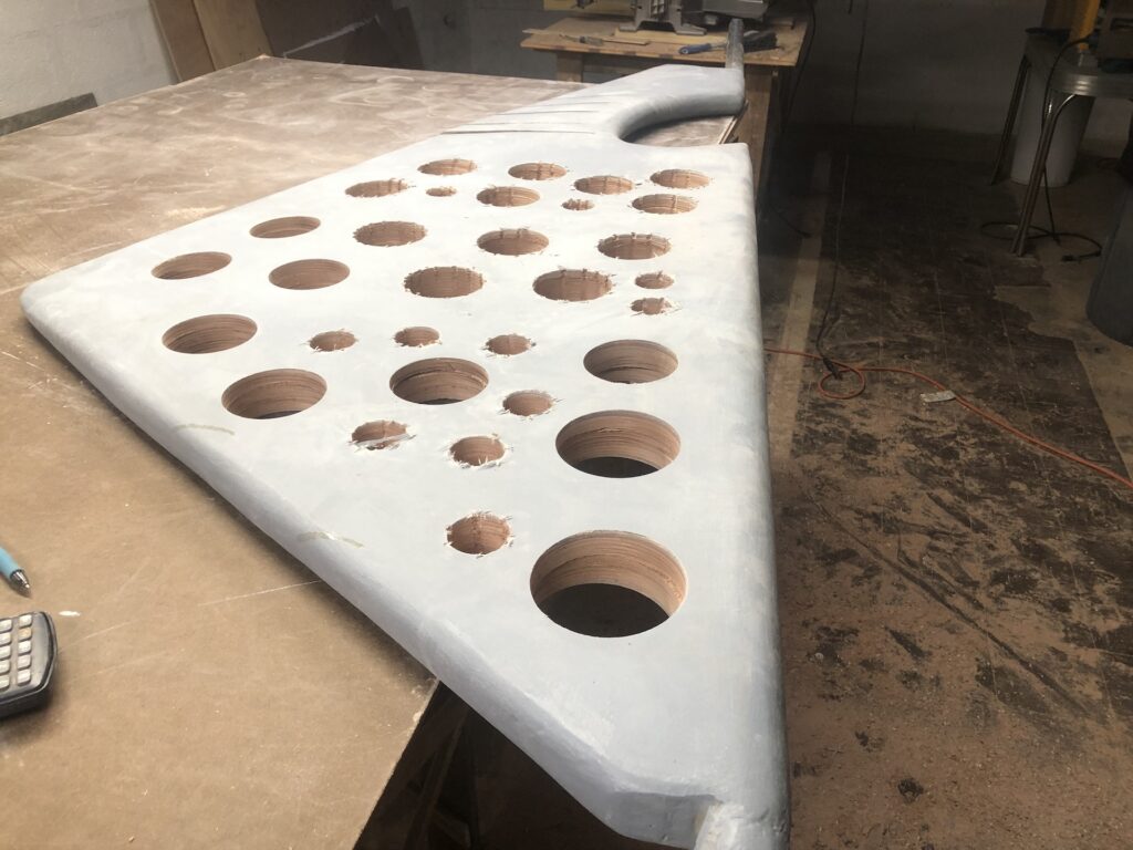
I removed about 20 pounds of material, and will add back perhaps half that. These holes will be easy to fill and glass over, and they will remain until later as they will be useful handholds for all of the dry-fits that will be required.
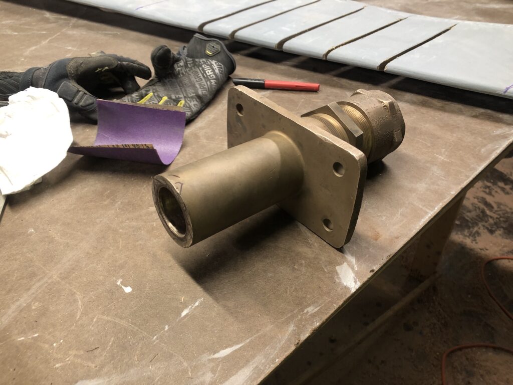
I removed the original rudder port in 2019 (click HERE for a review) and purchased the one below as a replacement. The rudder post is 1.75″ solid stainless steel, and the part below is properly sized.
Unfortunately, the rudder post is very, very slightly not straight, and there are various dings and divots. As a result the rudder port gets stuck well far from its proper position–well above that in the image below, in which I had already taken some corrective measures.
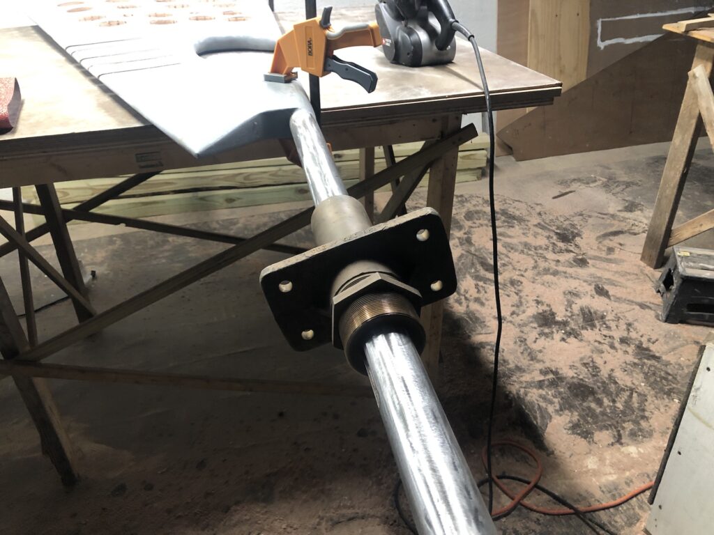
The corrective measures were a combination of sanding (with a belt sander, and a disc sander) and filing. The belt sanding generates a lot of friction heat, so before test fitting each time I cooled down the shaft to its not-thermally-expanded state.
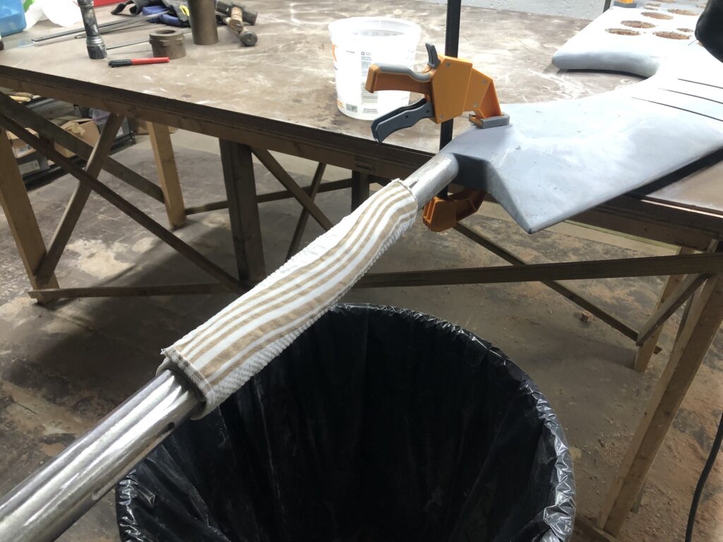
After many rounds of sanding, and many sanding belts and discs, I was able to bring the port within 5 inches of the top of the rudder, which I estimated to be sufficient.
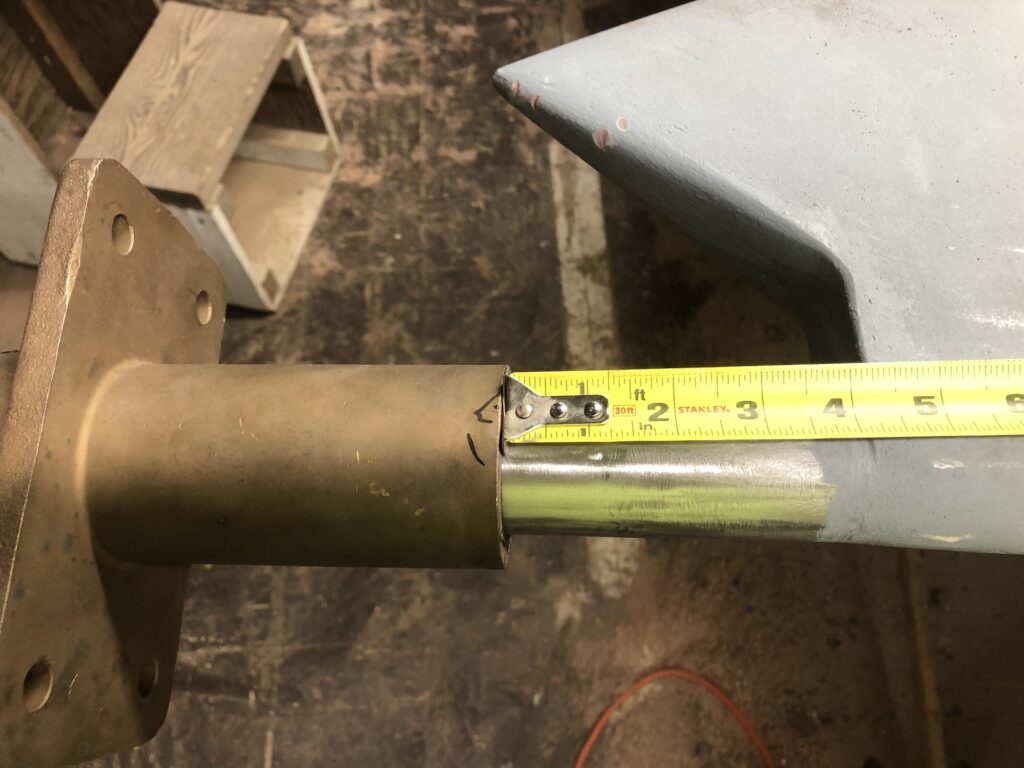
The rudder port itself will need a modification, but more on that later.
HEAD AND PLUMBING
Work has continued on the thru-hulls and the systems with which they connect. My last post discussed the five thru-hulls aft of the galley: Two for cockpit drains, two for bilge pumps, one for raw water engine intake.
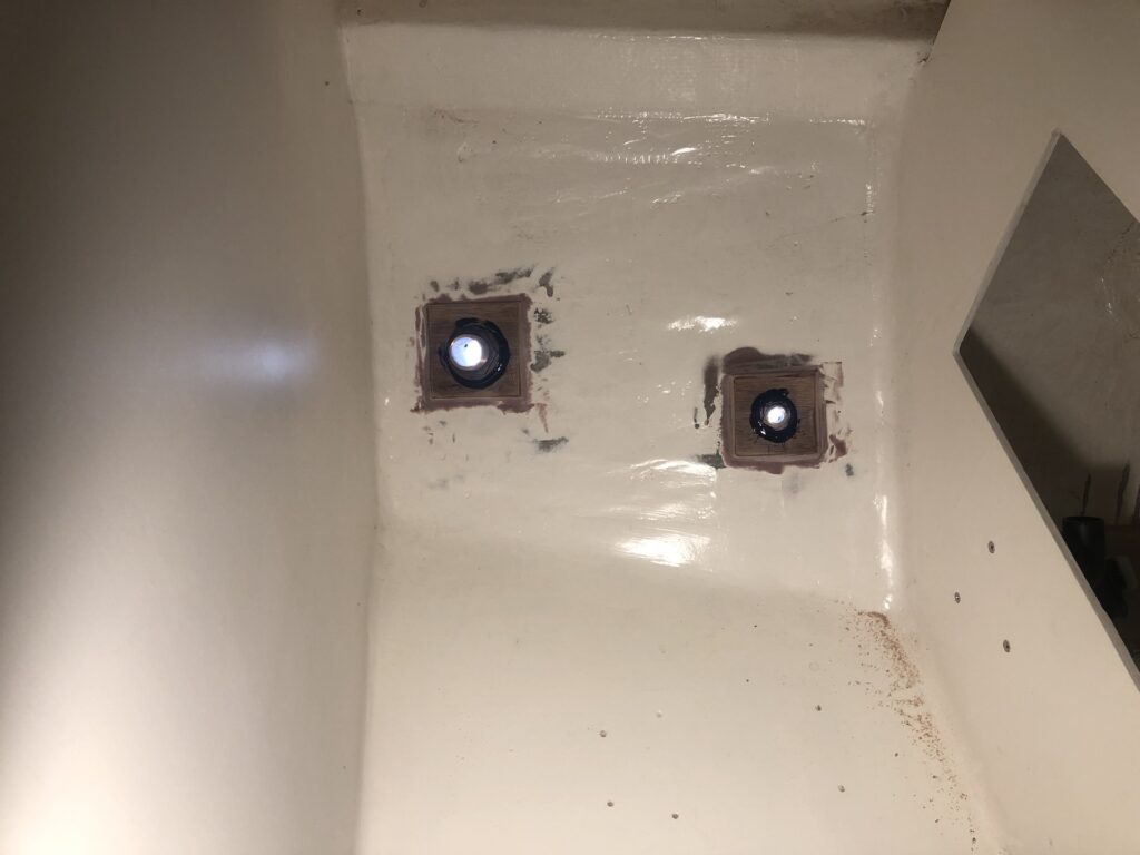
There are now four more: Galley sink drain, head sink drain, seawater in for toilet, black water out from holding tank. The image below shows black-water-out (left) and seawater in (right).
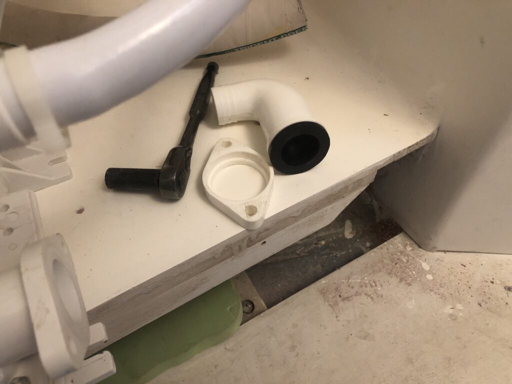
There is a lot of plumbing for the human-waste system on a boat. When the toilet is pumped to flush, seawater will enter the toilet. The waste exits the bowl through this fitting in the rear. The bolts that attach the barbed elbow can be loosened so the elbow can pivot to the desired orientation. You can see, however, that the bolts have “bottomed out” and thus are applying the maximum possible pressure to the gasket.
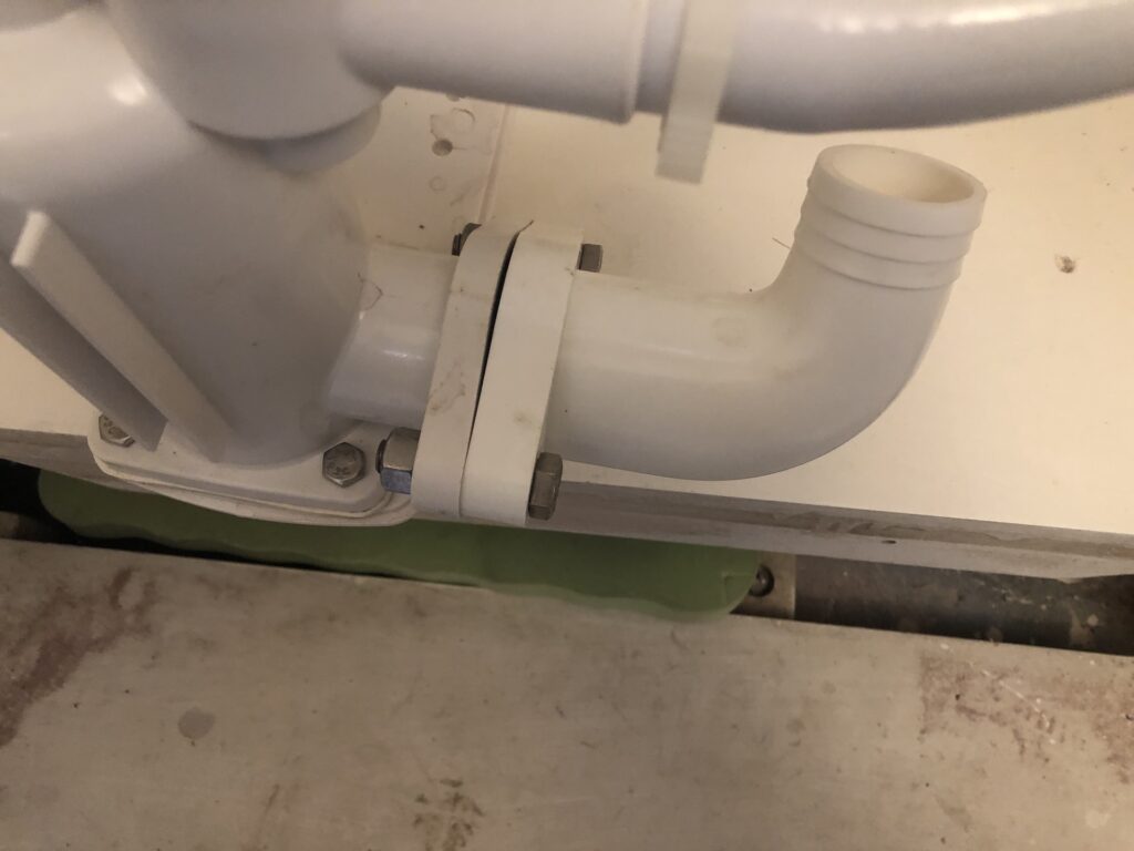
The replacement part for the elbow below and gasket is available at Defender, and I’ll order one soon.
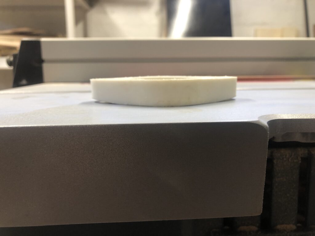
In the mean time, I took some corrective measures, and sanded back the “bottomed out” part of the flange, taking it from this…
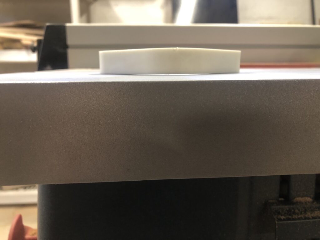
…to this:
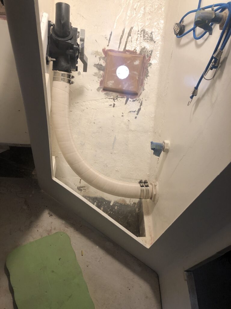
Waste goes from the toilet straight to the holding tank (that plumbing not shown). There will be two ways to empty the holding tank: (1) pump it out through a deck fitting, or (2) pump it into the sea (provided the boat is sufficiently offshore). The image below shows the double-clamped sanitation hose attached to the holding-tank-out port, and also to a Y-valve, whose setting will determine which of the two emptying options will be utilized.
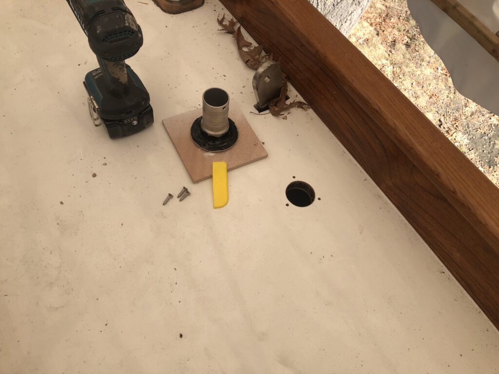
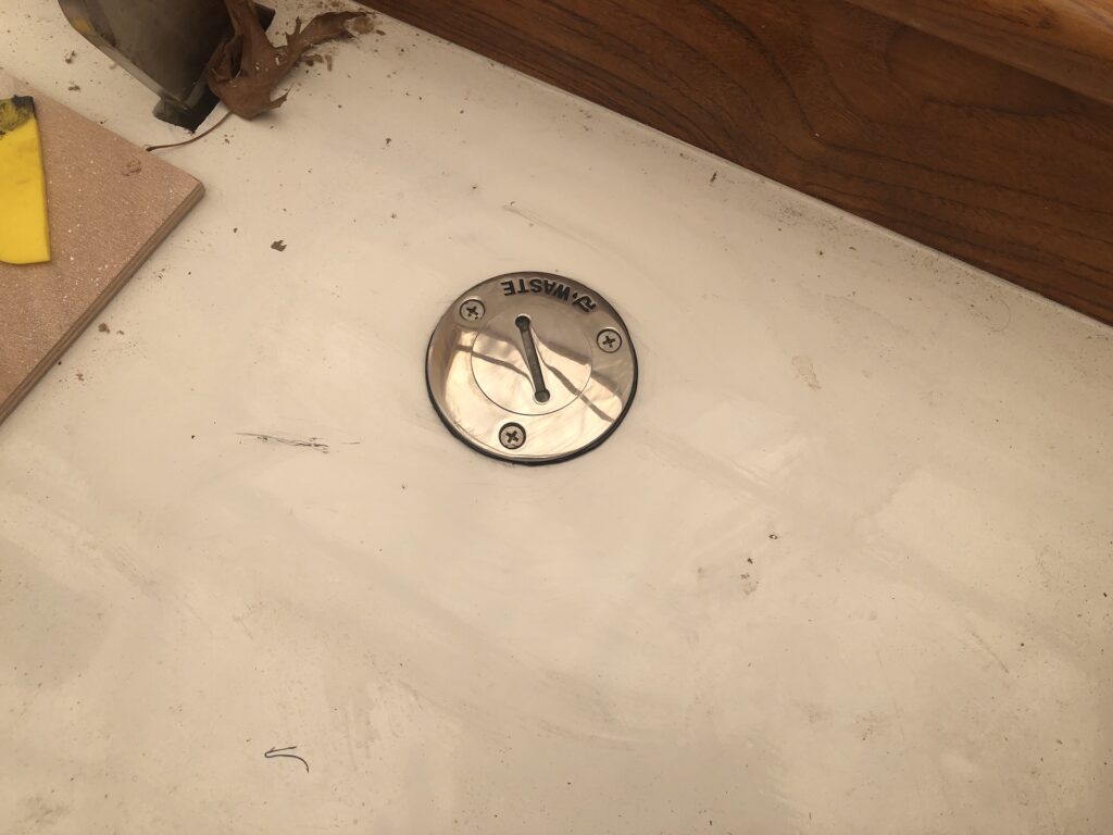
Here I’m installing the deck fitting for pumpout:
MOTOR
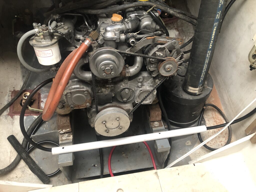
Work has continued on the motor and related systems (fuel, electrical, controls, etc.). I’ll report more extensively on this work in a future post.
